101(S)-5T & 101(S)-7T Series Hydraulic Steering Control Units

Load-sensing hydraulic steering control units designed for pipe-mounted priority valve systems. The 5T version uses a static load-sensing signal, while the 7T version uses a dynamic load-sensing signal.
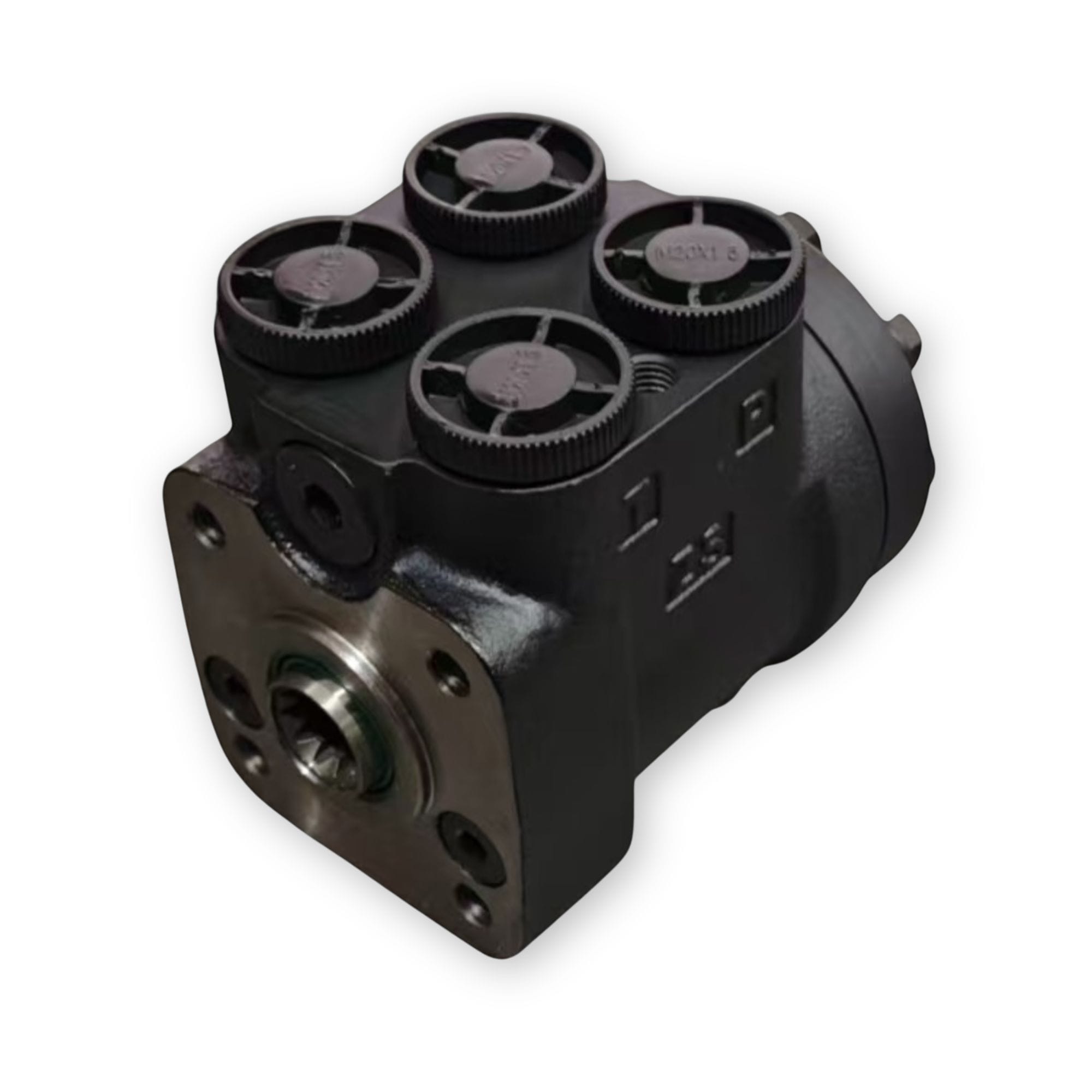
101S hydraulic steering control units

Description:

The 101(S)-5T and 101(S)-7T series are load-sensing hydraulic steering control units developed for pipe-mounted priority valve systems.

The 5T version uses a static load-sensing signal and is designed for use with YXL static-signal load-sensing priority valves. The 7T version uses a dynamic load-sensing signal and is designed for use with DYXL dynamic-signal load-sensing priority valves.

The product range includes 101 versions without integrated valves and 101S versions with integrated valve configurations. Available displacements range from 50 to 1000 mL/rev, supporting agricultural machinery, construction equipment and other mobile hydraulic steering systems.

Key Specifications

• Series: 101-5T, 101-7T, 101S-5T and 101S-7T
• Load-Sensing Type: Static signal or dynamic signal
• Priority Valve Connection: Pipe mounting
• Displacement Range: 50–1000 mL/rev
• Rated Flow Range: 5–75 L/min
• Max. Input Pressure: 17.5 MPa
• Max. Continuous Back Pressure: 2.5 MPa
• Integrated Valve Options: Available for 101S versions
• Port Codes: A, B, B2, C, D, E, U, M, F, F2, I, N, K, G, Q and J

Function Options

Choose the appropriate load-sensing function according to the priority-valve signal system used by the machine.

101(S)-5T — Static Signal Load Sensing

• Static load-sensing signal
• Pipe-mounted priority-valve connection
• Designed for use with YXL static-signal load-sensing priority valves
• Available as 101 without integrated valves or 101S with integrated valve configurations

101(S)-7T — Dynamic Signal Load Sensing

• Dynamic load-sensing signal
• Pipe-mounted priority-valve connection
• Designed for use with DYXL dynamic-signal load-sensing priority valves
• Available as 101 without integrated valves or 101S with integrated valve configurations

Displacement & Rated Flow Options

Compare available displacement, rated flow and overall unit length for preliminary selection.

Available Displacements: 50–1,000 mL/rev.

50 mL/rev.
  • Rated Flow: 5 L/min
  • Dimension L: 130 mm
63 mL/rev.
  • Rated Flow: 6 L/min
  • Dimension L: 131 mm
80 mL/rev.
  • Rated Flow: 8 L/min
  • Dimension L: 133.5 mm
100 mL/rev.
  • Rated Flow: 10 L/min
  • Dimension L: 136 mm
125 mL/rev.
  • Rated Flow: 12.5 L/min
  • Dimension L: 139 mm
160 mL/rev.
  • Rated Flow: 16 L/min
  • Dimension L: 144 mm
200 mL/rev.
  • Rated Flow: 20 L/min
  • Dimension L: 149 mm
250 mL/rev.
  • Rated Flow: 25 L/min
  • Dimension L: 155 mm
280 mL/rev.
  • Rated Flow: 28 L/min
  • Dimension L: 160 mm
315 mL/rev.
  • Rated Flow: 31.5 L/min
  • Dimension L: 165 mm
370 mL/rev.
  • Rated Flow: 37 L/min
  • Dimension L: 172 mm
400 mL/rev.
  • Rated Flow: 40 L/min
  • Dimension L: 175 mm
500 mL/rev.
  • Rated Flow: 50 L/min
  • Dimension L: 187 mm
630 mL/rev.
  • Rated Flow: 50 L/min
  • Dimension L: 212 mm
740 mL/rev.
  • Rated Flow: 56 L/min
  • Dimension L: 226 mm
800 mL/rev.
  • Rated Flow: 60 L/min
  • Dimension L: 232 mm
1,000 mL/rev.
  • Rated Flow: 75 L/min
  • Dimension L: 256 mm

Pressure & Integrated Valve Settings

Confirm the operating pressure requirements and integrated valve settings according to the steering circuit. Integrated valve settings apply to 101S versions.

Maximum Input Pressure

• Maximum pressure: 17.5 MPa
• Applies to the listed 101 and 101S configurations

Maximum Continuous Back Pressure

• Maximum continuous back pressure: 2.5 MPa
• Confirm the return-line condition before selection

Relief Valve Settings

• For 101S integrated valve versions
• Available settings: 6, 7, 8, 10, 12, 14, 15, 16 and 17.5 MPa

Shock Valve Settings

• Available settings: 12, 13, 14, 16, 18, 20, 21, 22 and 23.5 MPa
• The corresponding setting is 6 MPa higher than the selected relief valve setting

Port & Mounting Options

Review available port threads, mounting connections and oil-port connection options for preliminary configuration.

Metric Port Options

• M18×1.5
• M20×1.5
• M22×1.5
• Straight-thread and O-ring options

BSPP & UNF Port Options

• G1/2
• G1/2 O-ring
• 3/4-16UNF O-ring
• 9/16-18UNF O-ring

Mounting Connection Options

• M10 flange connection
• M10×1.25 flange connection
• 3/8-16UNC flange connection
• Multiple mounting thread configurations

Oil Port Connection Threads

• M12 connection thread
• M10 and M10×1 connection threads
• 3/8-24UNF connection thread
• Port-code-specific configurations

Port and mounting configurations depend on the selected port code. Please provide the existing model, nameplate, port dimensions, flange connection threads and application requirements for final confirmation.

Reference depths: P, T, L and R ports — 15 mm; column mounting C and V — 16 mm; LS port — 12 mm.

How to Specify a 101(S)-5T / 7T Steering Control Unit

101 Version — Without Integrated Valve

Order code structure:

101-[5 or 7]T-[Displacement]-[Port Code]

5T: Static signal load sensing, pipe mounting
7T: Dynamic signal load sensing, pipe mounting

Example: 101-5T-125-E

101S Version — With Integrated Valve

Order code structure:

101S-[5 or 7]T-[Displacement]-[Relief Valve Setting]-[Port Code]

5T: Static signal load sensing, pipe mounting
7T: Dynamic signal load sensing, pipe mounting

Example: 101S-5T-125-10-E

Information Required for Model Selection


• 5T static signal or 7T dynamic signal

• 101 version or 101S integrated valve version

• Required displacement

• Required relief valve setting for 101S versions

• Port code or complete thread requirements

• Existing model number or nameplate photo

• Machine application and operating conditions

Designed for Reliable Steering Performance

Static or Dynamic Load-Sensing Options

Choose the 5T static-signal version or the 7T dynamic-signal version according to the priority-valve system.

Broad Displacement Range

Seventeen displacement options from 50 to 1,000 mL/rev. support different steering cylinder capacities and machine requirements.

Integrated Valve Version Available

101S versions are available with integrated relief and shock valve settings for different steering circuit requirements.

Flexible Port and Mounting Options

Multiple metric, BSP and UNF/UNC port and mounting thread combinations are available for OEM and replacement applications.

Applications

Agricultural Machinery
Construction Equipment
Mobile Hydraulic Systems

Need Help Matching a Model?

Send us the existing model number, photos, nameplate information, operating pressure, flow rate and application details. YUNLINK can support model matching, replacement selection and quotation.

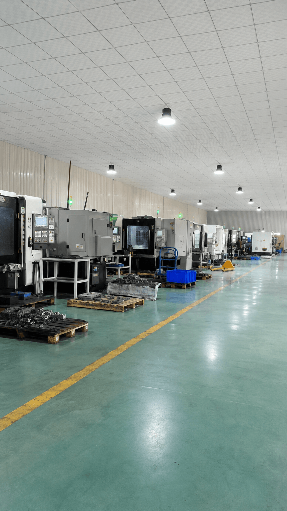
YUNLINK hydraulic components production workshop and inquiry support
CONTACT FORM

Get in touch today

Tell us your required hydraulic components, quantity and application. Our team will reply as soon as possible.

Please include product model, quantity and application if available.