FJF06-01 Flow Divider/Combiner Valve

The FJF06-01 pressure-compensated flow divider/combiner valve is designed to divide inlet flow from the V port equally between C1 and C2, and to combine return flows when the direction is reversed. It supports synchronized hydraulic operation in compact mobile machinery and industrial hydraulic systems.
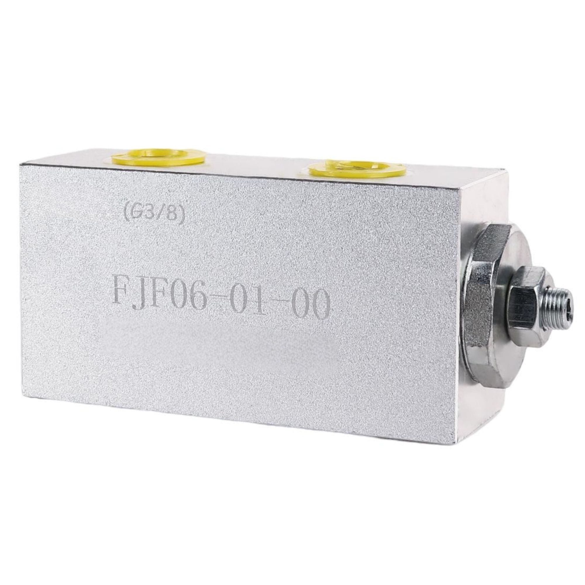
FJF06 flow divider combiner valve for hydraulic flow distribution

Description:

The FJF06-01 is a pressure-compensated flow divider/combiner valve designed for hydraulic circuits requiring equal flow distribution and reverse-flow combining.

In dividing mode, inlet flow from the V port is divided between the C1 and C2 ports at a 50% ratio. When the flow direction is reversed, flows from C1 and C2 are combined through the common V port.

The valve supports flow rates from 2.8 to 30 L/min and maximum working pressure up to 210 bar. It is suitable for synchronized cylinder circuits, compact mobile machinery and industrial hydraulic systems.

Key Specifications

• Model: FJF06-01
• Valve Type: Pressure-compensated flow divider/combiner valve
• Dividing Mode: V inlet to C1 and C2
• Combining Mode: C1 and C2 return to V
• Flow Division Ratio: 50%
• Flow Range: 2.8–30 L/min
• Maximum Working Pressure: 210 bar
• Standard Porting Code: 01
• Standard Port Size: G3/8 for V, C1 and C2
• Seal / Temperature: NBR, −30°C to +80°C
• Other Porting Options: Available on request

Dividing & Combining Operation

Review how the FJF06-01 divides inlet flow between C1 and C2 and combines the two return flows through the common V port.

Dividing Mode

• Inlet flow enters through the V port
• Flow is divided between C1 and C2
• Standard flow division ratio: 50%
• Designed for synchronized actuator operation

Combining Mode

• Reverse flows enter through C1 and C2
• The two flows are combined through the common V port
• Supports bidirectional hydraulic circuit operation
• Confirm circuit flow and pressure before selection

FJF06-01 Technical Performance

Review the main pressure, flow, division ratio and operating-temperature specifications for the FJF06-01 flow divider/combiner valve.

Maximum Working Pressure

• Maximum working pressure: 210 bar
• Confirm the actual circuit pressure before selection

Flow Range

• Minimum flow: 2.8 L/min
• Maximum flow: 30 L/min
• Select according to total inlet flow

Flow Division Ratio

• Standard division ratio: 50%
• Equal flow distribution between C1 and C2
• No synchronization accuracy value is specified in the current datasheet

Temperature & Filtration

• Seal material: NBR
• Operating temperature: −30°C to +80°C
• Filtration requirement: Confirm with YUNLINK before ordering

Port, Dimensions & Model Selection

Confirm the standard porting, port functions, installation space, flow requirement and working pressure before selecting the FJF06-01 valve.

Standard Porting

• Standard porting code: 01
• V, C1 and C2 ports: G3/8
• Other porting options are available on request
• Confirm the required thread before ordering

Port Functions

• V: Common inlet in dividing mode
• C1 and C2: Divided outlet ports
• In reverse operation, C1 and C2 combine to V
• Confirm the required circuit direction

Main Installation Dimensions

• Overall body length: 115 mm
• Overall body height: 60 mm
• Confirm the available installation space
• Refer to the PDF for the complete sectional drawing

Selection Information

• Required total inlet flow
• Maximum working pressure
• Port size and thread requirement
• Installation dimensions and machine application

For new-system or replacement selection, please provide the existing valve model, required flow, working pressure, port specification, installation space and application details.

Standard FJF06-01 porting is G3/8 for V, C1 and C2. Other porting options must be confirmed before ordering.

Designed for Reliable Flow Division and Combining

Pressure-Compensated Operation

Helps maintain the specified flow division ratio across changing hydraulic circuit pressure conditions.

Bidirectional Flow Control

Divides inlet flow from V to C1 and C2 and combines reverse flows from C1 and C2 through the common V port.

Equal 50% Flow Division

Provides equal flow distribution between the C1 and C2 branches for synchronized hydraulic actuator circuits.

Compact Installation

Compact valve body with G3/8 standard porting supports installation in mobile and industrial hydraulic systems.

Applications

Compact Mobile Machinery
Industrial Hydraulic Systems
Synchronized Cylinder Circuits

Need Help Selecting a Flow Divider / Combiner Valve?

• Existing valve model
• Required total inlet flow
• Maximum working pressure
• Required flow division ratio
• Port size and thread type
• Installation dimensions
• Machine application

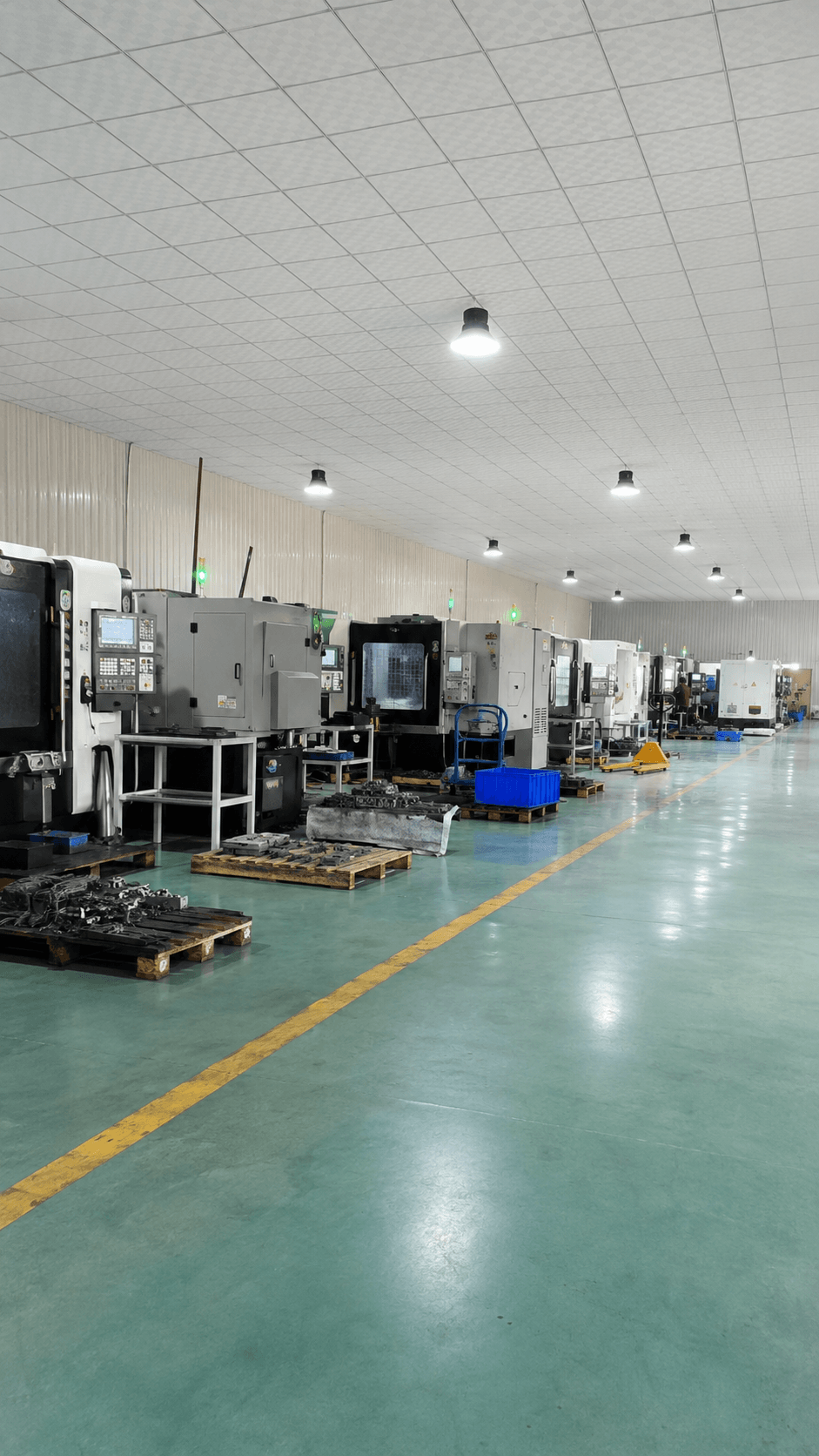
YUNLINK hydraulic components production workshop and inquiry support
CONTACT FORM

Get in touch today

Tell us your required hydraulic components, quantity and application. Our team will reply as soon as possible.

Please include product model, quantity and application if available.