VBCD Series Double-direction Counterbalance Valve

YUNLINK VBCD double-direction counterbalance valves are available in DE/A, DE/G, DE/FL and VBCD3801S configurations for bidirectional hydraulic load-control circuits. Depending on the model, maximum flow reaches 160 L/min, maximum pressure reaches 350 bar, and pilot ratios range from 4.25:1 to 6.2:1, with BSPP, metric, flange-mounted and inch-port options.
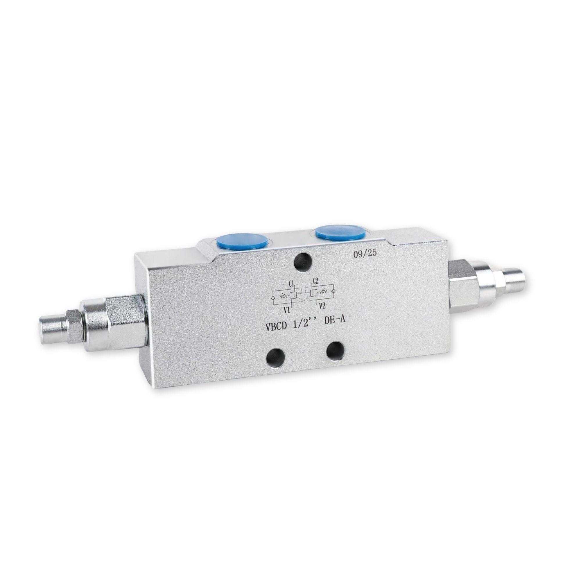
VBCD double direction counterbalance valve for lifting hydraulic systems

Description:

VBCD double-direction counterbalance valves use two pressure-control sections to manage hydraulic actuator flow in both directions. The range includes DE/A, DE/G, DE/FL and VBCD3801S configurations, with model-specific flow, pressure, pilot ratio, connection and mounting data.

Depending on the model, maximum flow ranges from 20 to 160 L/min and maximum pressure is up to 350 bar. Available pilot ratios include 4.25:1, 4.5:1, 5.5:1 and 6.2:1, with BSPP, metric, flange-mounted and inch-size configurations. Select the valve according to required flow, working pressure, pilot ratio, port type and mounting dimensions.

Key Specifications

  • Product Type: Double-direction counterbalance valve
  • Available Configurations: VBCD DE/A, DE/G, DE/FL and VBCD3801S
  • Maximum Working Pressure: Up to 350 bar, depending on configuration and body material
  • Maximum Flow: 20 to 160 L/min, depending on model
  • Pilot Ratio Options: 4.25:1, 4.5:1, 5.5:1 and 6.2:1
  • BSPP Port Options: G1/4, G3/8, G1/2, G3/4 and G1
  • Metric Port Options: M14×1.5, M18×1.5 and M22×1.5
  • Other Configurations: Flange-mounted DE/FL and VBCD3801S inch-port models
  •  

Series & Model Options

VBCD DE/A Threaded Series

BSPP models are available from G1/4 to G1, with maximum flow ratings from 20 to 160 L/min. All listed DE/A models have a maximum pressure rating of 350 bar.

VBCD DE/G Series

DE/G models cover maximum flow ratings from 20 to 60 L/min with a 4.5:1 pilot ratio. Steel and aluminium body pressure ratings are listed separately in the datasheet.

VBCD DE/FL Flange-Mounted Series

Flange-mounted models are available in G3/8 and G1/2 sizes, with maximum flow ratings of 40 or 60 L/min and a 4.25:1 pilot ratio.

VBCD3801S Inch-Port Series

VBCD3801S models are available in 1/4, 3/8 and 1/2 inch sizes. The datasheet provides model-specific dimensions and a separate hydraulic symbol.

Connection & Mounting Options

BSPP Threaded Ports

DE/A threaded models are available with BSPP port sizes from G1/4 to G1, including G1/4, G3/8, G1/2, G3/4 and G1.

Metric Thread Options

Metric threaded configurations include M14×1.5, M18×1.5 and M22×1.5, corresponding to selected 20, 40 and 60 L/min models.

DE/FL Flange Mounting

DE/FL models are available with G3/8 or G1/2 ports, Ø9 mounting holes and model-specific O-ring dimensions.

VBCD3801S Inch Ports

VBCD3801S configurations are available in 1/4, 3/8 and 1/2 inch sizes. Confirm the dimensional drawing before installation or replacement.

Flow, Pressure & Pilot Ratio Selection

DE/A Flow & Pressure Range

DE/A models cover maximum flow ratings from 20 to 160 L/min. All listed DE/A models have a maximum pressure rating of 350 bar.

DE/G Pressure Ratings

DE/G models cover maximum flow ratings from 20 to 60 L/min with a 4.5:1 pilot ratio. Steel versions are rated up to 350 bar and aluminium versions up to 210 bar.

DE/FL Flange Ratings

DE/FL models are rated at 40 or 60 L/min with a 4.25:1 pilot ratio. Steel versions are rated up to 350 bar and aluminium versions up to 210 bar.

Model-Specific Pilot Ratios

Pilot ratios vary by configuration and size: 4.25:1, 4.5:1, 5.5:1 or 6.2:1. Confirm the selected model together with flow, pressure and load conditions.

Hydraulic Function & Bidirectional Flow Control
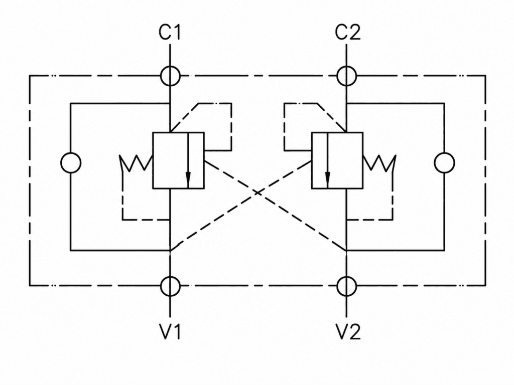
Free flow: Flow from V1 to C1 and from V2 to C2 passes through the integrated check valves toward the actuator.

Controlled return flow: Reverse flow from C1 to V1 and from C2 to V2 passes through the corresponding counterbalance sections.

Cross-pilot release: Pressure at V1 pilots the C2-to-V2 section open, while pressure at V2 pilots the C1-to-V1 section open.

Double-direction Counterbalance Valve Hydraulic Symbol

How to Specify a Double-direction Counterbalance Valve

1. Required Flow
Specify the maximum flow required in both directions of the hydraulic circuit.

2. Working Pressure & Body Material
Confirm the maximum working pressure and whether a steel or aluminium body configuration is required.

3. Pilot Ratio
Select the pilot ratio according to the required series, model size, load conditions and available pilot pressure.

4. Port Size & Connection Type
Confirm the required BSPP, metric, flange-mounted or inch-size connection.

5. Series & Mounting Configuration
Choose between DE/A, DE/G, DE/FL or VBCD3801S according to the port arrangement and mounting dimensions.

6. Model & Application Details
Provide the existing valve model, hydraulic schematic, required flow, pressure, mounting dimensions and equipment application when requesting a replacement.

Designed for bidirectional load control

Load Control in Both Directions

Two counterbalance sections control return flow from both actuator ports according to the selected valve setting and pilot condition.

Cross-Pilot Operation

Pressure at V1 assists the C2-to-V2 section, while pressure at V2 assists the C1-to-V1 section.

Free Flow Toward the Actuator

Integrated check-valve paths allow flow from V1 to C1 and from V2 to C2 toward the actuator.

Model-Based Configuration

Select the valve according to required flow, working pressure, pilot ratio, port type, body material and mounting dimensions.

Applications

Mobile Machinery Hydraulic Systems
Industrial Hydraulic Systems
Bidirectional Cylinder Load-Control Circuits

Need Help Selecting a Double-direction Counterbalance Valve?

Send us the existing valve model, hydraulic schematic, required flow, working pressure, pilot ratio, port type, body material, mounting dimensions and equipment application. Our team can review the information and help match a suitable DE/A, DE/G, DE/FL or VBCD3801S configuration for quotation.

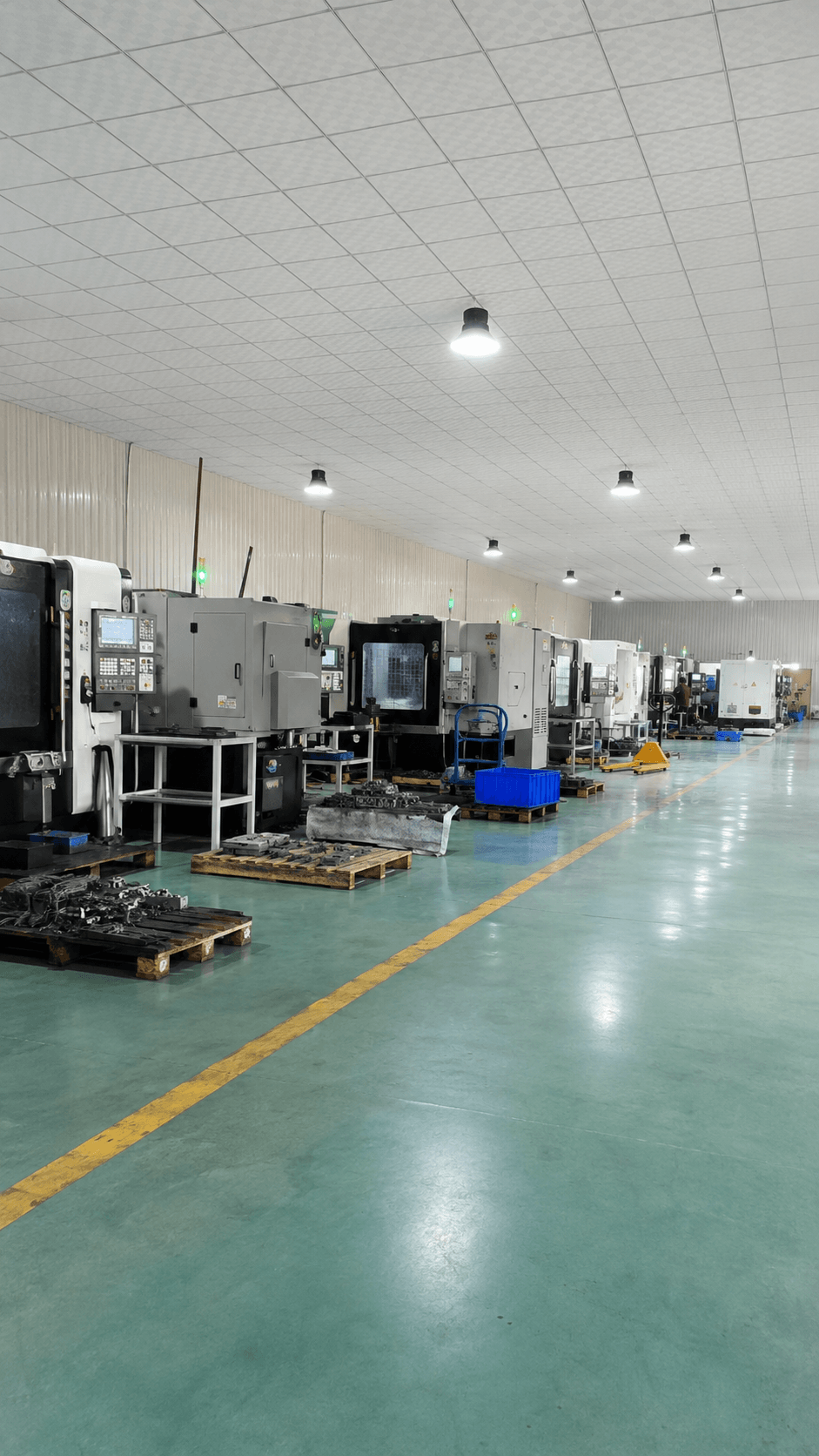
YUNLINK hydraulic components production workshop and inquiry support
CONTACT FORM

Get in touch today

Tell us your required hydraulic components, quantity and application. Our team will reply as soon as possible.

Please include product model, quantity and application if available.