
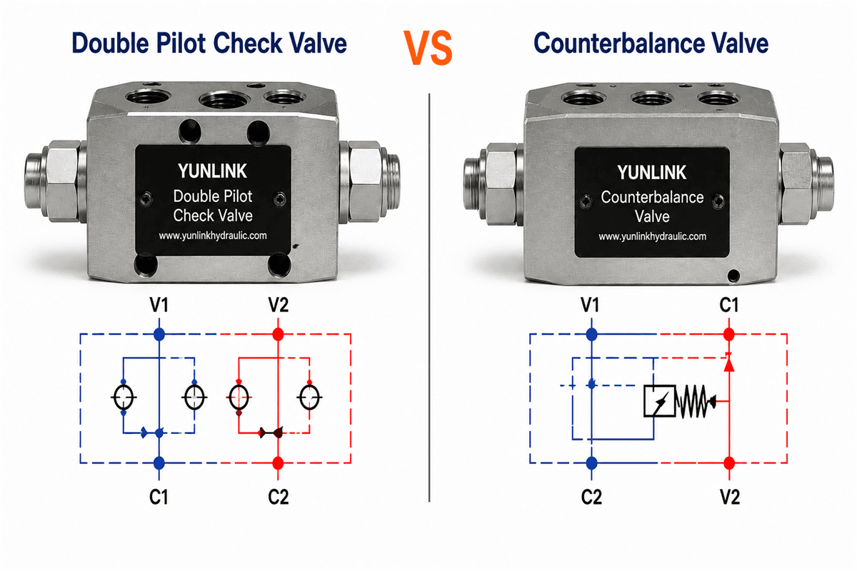

Double pilot check valve vs counterbalance valve selection depends on the hydraulic function required in the cylinder circuit. Both valve types can be used where load holding is important, but they perform different control functions and should not be treated as interchangeable components without reviewing the complete hydraulic circuit.
The main distinction is straightforward: a double pilot check valve is primarily used to lock flow in both cylinder lines until pilot pressure releases the appropriate check valve, while a counterbalance valve is designed to support a load and control an overrunning load during movement. Understanding this difference helps prevent unstable lowering, unwanted movement and incorrect valve replacement.
Double Pilot Check Valve vs Counterbalance Valve: Quick Comparison
A double pilot check valve is usually selected when the main requirement is bidirectional cylinder locking. It blocks reverse flow from both actuator ports and opens a check valve when pilot pressure is received from the opposite line.
A counterbalance valve is normally selected when the actuator must hold a load and also lower or move it in a controlled way. The valve maintains back pressure and responds to pilot pressure so that an overrunning load does not drive the actuator faster than the supplied flow.
Both valve types are pilot operated, but their internal functions and adjustment requirements are different.
How a Double Pilot Check Valve Works
A double pilot check valve combines two pilot-operated check functions in one body. Free flow is allowed toward the actuator through the check valves. Return flow remains blocked until pressure in the opposite line acts on the pilot section and opens the required check valve.
This arrangement is commonly used to hold a double-acting cylinder in position when the directional valve is centered or the pump is stopped. Because both actuator lines are checked, the valve can support locking in either direction.
The valve should normally be installed close to the actuator when hose-failure protection and reduced trapped-line movement are important. Actual holding performance still depends on the valve, cylinder seals, fittings and the condition of the complete hydraulic circuit.
Explore the YUNLINK Double Pilot Check Valve product page for available series, port options and model-selection information.
How a Counterbalance Valve Works
A counterbalance valve combines load holding with pressure control. It restricts return flow from a loaded actuator until the pilot pressure and load-induced pressure reach the valve’s opening condition.
When a vertical cylinder lowers a load, gravity may try to move the cylinder faster than the pump supplies oil. This is known as an overrunning load. A correctly selected counterbalance valve helps maintain back pressure and meters the return flow so that the movement remains controlled.
Counterbalance valves may be used for one-direction or bidirectional control, depending on the circuit and valve configuration. Their selection requires attention to flow, maximum pressure, pilot ratio, setting or opening condition, port size, mounting arrangement and the dynamic behavior of the machine.
For more background, read What Is a Counterbalance Valve and Where Is It Used? and the Counterbalance Valve Selection Guide.
The Most Important Functional Differences
Primary purpose
A double pilot check valve primarily locks the actuator lines. A counterbalance valve holds the load while also controlling an overrunning load during movement.
Flow control during lowering
A pilot check valve releases the blocked flow path when sufficient pilot pressure is available. It is not normally intended to meter an overrunning load through the full lowering cycle.
A counterbalance valve opens in a controlled relationship with pilot pressure and load pressure. This makes it more suitable for vertical cylinders, booms, platforms and other applications where gravity or inertia can drive the actuator.
Adjustment
Many double pilot check valves use a fixed internal design determined by the selected series and pilot ratio. Counterbalance valves often require a setting or opening condition matched to the load and circuit.
Circuit sensitivity
Both valve types depend on available pilot pressure and correct port connections. Counterbalance circuits are particularly sensitive to pilot ratio, back pressure, valve setting, flow demand and machine dynamics.
Replacement decisions
Matching only the port size or external dimensions is not enough. A replacement must also match the required hydraulic function, pressure capability, flow range, pilot arrangement and mounting pattern.
Choose a Double Pilot Check Valve When
Consider a double pilot check valve when:
- The cylinder must be locked hydraulically in both directions.
- The load is mainly static after the actuator reaches position.
- The circuit does not require the valve to control a continuously overrunning load.
- Compact inline or manifold-mounted locking is required close to the actuator.
- The available pilot pressure is sufficient to release the selected valve under the expected load conditions.
Typical examples include positioning cylinders, clamping circuits and equipment where an actuator must remain in place after the directional valve returns to neutral.
Choose a Counterbalance Valve When
Consider a counterbalance valve when:
- A vertical or inclined cylinder must lower a load smoothly.
- Gravity or inertia can drive the actuator faster than the pump flow.
- The circuit needs both load holding and controlled return flow.
- A boom, platform, lifting mechanism or similar load must remain stable during movement.
- Valve setting and pilot ratio need to be matched to the operating load and circuit pressure.
Depending on the machine, a single-direction counterbalance valve may control one loaded direction, while a double-direction configuration may be required when load control is needed in both directions.
Why a Pilot Check Valve May Not Replace a Counterbalance Valve
Replacing a counterbalance valve with a pilot check valve can remove the metering function needed for controlled lowering. Once the check valve is piloted open, an overrunning load may drive the actuator unless another component controls the return flow.
The opposite substitution can also create problems. Installing a counterbalance valve where only simple locking is required may add unnecessary pressure loss, heat and adjustment complexity if it is not selected for the circuit.
For this reason, identify the original valve function before comparing model numbers. The hydraulic schematic and machine behavior are usually more useful than the external appearance alone.
Information Needed for Valve Selection
Provide the following information when requesting a recommendation or replacement:
- Existing valve model or clear photos of all markings.
- Hydraulic schematic showing C1, C2, V1, V2 or equivalent port connections.
- Required flow and maximum working pressure.
- Cylinder bore, rod diameter and operating load where available.
- Direction of the load and whether it can overrun the pump flow.
- Pilot ratio or original valve setting, if known.
- Port standard and thread size.
- Inline, manifold, flange or cartridge mounting requirement.
- Installation dimensions and available space.
- Machine type and a short description of the operating cycle.
These details help determine whether the circuit requires a double pilot check valve, a single-direction counterbalance valve or a double-direction counterbalance solution.
Final Selection Guidance
When making a double pilot check valve vs counterbalance valve selection, use a double pilot check valve when the main objective is bidirectional cylinder locking and the circuit does not rely on the valve to control an overrunning load. Use a counterbalance valve when the actuator must hold a load and remain controlled while gravity or inertia drives movement.
Final selection should always be checked against the valve datasheet, the hydraulic schematic and the actual operating conditions. Do not apply the pressure, flow, pilot-ratio or temperature data of one series to every valve family.
Need help reviewing a valve circuit? Send YUNLINK your model number, hydraulic schematic, flow, pressure, pilot ratio, port details, mounting method and application information through the inquiry form.