
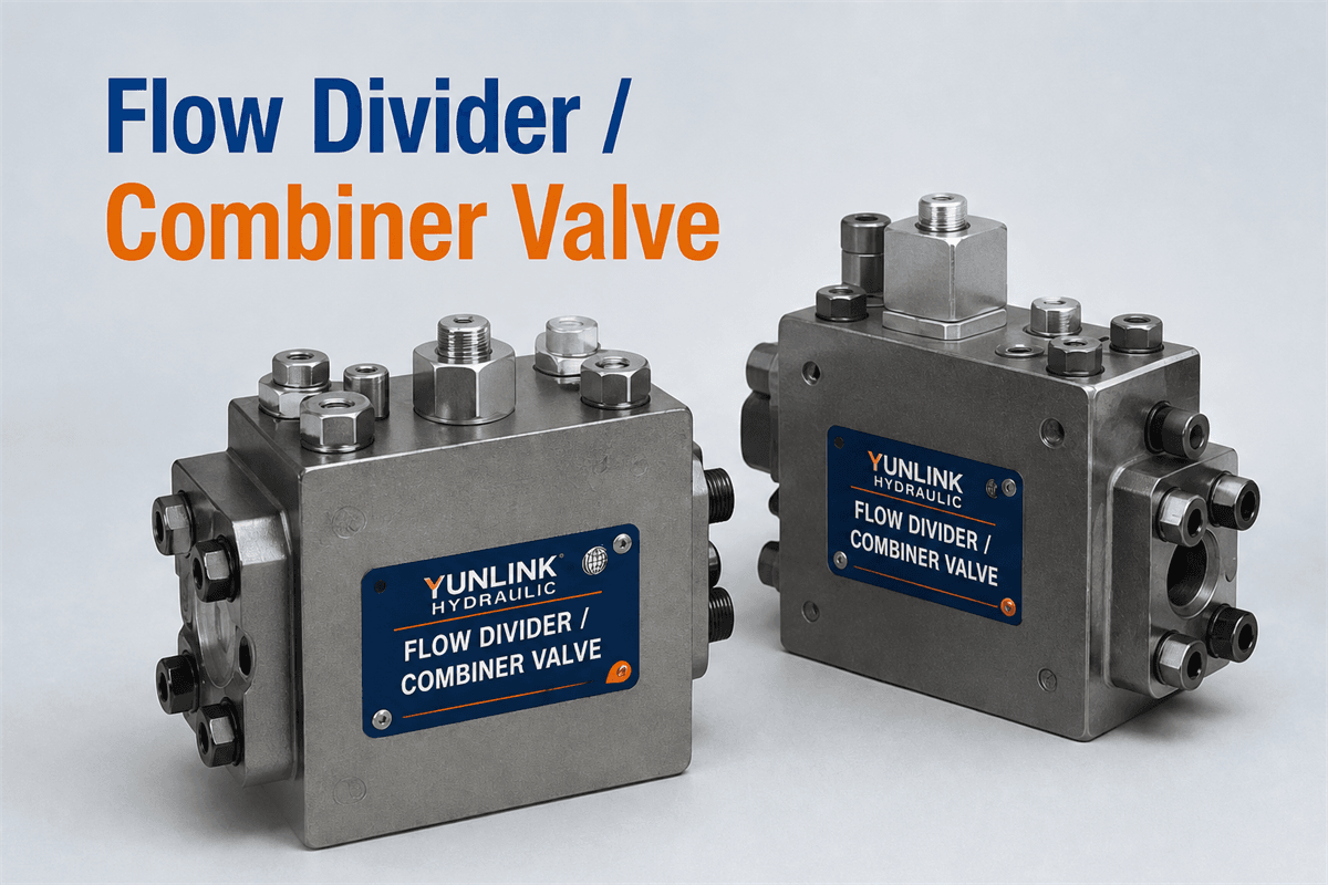

Selecting the right flow divider and combiner valve is important when a hydraulic system must distribute pump flow to two or more actuators, or return combined actuator flow through one circuit. For equipment manufacturers, hydraulic-system designers, and replacement-part buyers, the decision should be based on the circuit duty, required flow ratio, pressure conditions, and acceptable synchronization error—not on port size alone.
This guide explains the practical checks that help buyers compare a flow divider and combiner valve with the needs of agricultural machinery, construction equipment, material-handling systems, and other mobile or industrial hydraulic applications.
What a Flow Divider and Combiner Valve Does
A flow divider and combiner valve divides an incoming oil flow into two or more proportional outlet flows. In the reverse direction, it can combine return flows from separate branches into a common line. These functions can simplify circuit routing where two hydraulic motors or cylinders need a controlled flow relationship.
The valve does not automatically make every pair of actuators move at exactly the same speed. Actual movement can still be affected by load differences, internal leakage, oil temperature, relief-valve settings, and the mechanical resistance of the machine. A suitable selection therefore starts with the required function and the allowable performance variation.
Start With the Circuit Function
Before choosing a model, identify how the valve will work in the real circuit.
- Flow division: One pump supply is split between two or more working branches.
- Flow combination: Return or supply flow from separate branches is combined into one line.
- Bidirectional operation: The circuit needs stable divider/combiner behavior when the direction of oil flow reverses.
- Priority function: One branch must receive a defined portion of the available flow before another branch operates.
For example, a two-section valve with a 50:50 ratio may be appropriate when two branches require equal nominal flow. A 60:40 or other unequal ratio may be more suitable where actuator displacement or required operating speed differs. Confirm the required ratio from the hydraulic schematic rather than assuming equal flow is correct.
Match the Required Flow Range and Ratio
The rated flow of the valve must cover the normal operating flow and the expected peak flow without forcing the valve to work continuously at the edge of its range. Very low flow can reduce dividing accuracy, while excessive flow may increase pressure loss and heat generation.
When comparing models, verify these points with the supplier’s technical data:
- Minimum, nominal, and maximum operating flow for each section.
- The specified flow ratio and whether it is equal or unequal.
- The permitted deviation from the nominal ratio under stated test conditions.
- Whether the stated accuracy applies to dividing, combining, or both directions.
- The oil viscosity and temperature range used for the published performance data.
For replacement projects, compare the original valve’s total flow rating and section ratio with the new candidate. A matching thread or flange pattern does not confirm that the flow characteristic is compatible.
Check Pressure Rating and Load Conditions
Pressure capability must be evaluated at the valve and in each downstream branch. The valve should be rated for the system’s normal working pressure, predictable pressure peaks, and the relief-valve setting. Also consider whether one branch may experience a much higher load than the other.
Large load differences can affect how a flow divider and combiner valve behaves. In some circuits, cross-port relief valves, anti-cavitation protection, load-holding components, or additional circuit controls may be necessary. These components should be selected as a complete circuit, not added after a divider valve has already been specified.
Ask for the pressure-drop curve at the actual intended flow. A valve that appears suitable by its maximum pressure rating can still create an unacceptable pressure loss if the section size is too small for the required flow.
Consider Synchronization and Accuracy Expectations
Flow dividers help maintain a proportional flow relationship, but they are not a substitute for closed-loop position control where highly precise synchronization is required. Cylinder area tolerances, unequal loads, mechanical binding, and leakage can cause position differences to accumulate over a long operating cycle.
For applications such as folding equipment, lifting platforms, or dual-motor drives, define the acceptable mismatch before selecting the valve. If the application needs exact position matching, sensor feedback and electro-hydraulic control may be more appropriate than a purely hydraulic divider solution.
Select the Correct Number of Sections and Port Arrangement
Choose the number of sections from the circuit layout: two sections for two branches, three sections for three branches, and so on. More sections can reduce external manifolding but may also increase installation space, plumbing complexity, and the number of conditions that need to be checked during commissioning.
Port type, port size, mounting method, and flow direction must all match the actual installation. Verify:
- Inlet, outlet, and combined-flow port identification.
- Thread standard or flange interface.
- Maximum permitted tightening torque and connection method.
- Clearance for hoses, fittings, and service access.
- The required mounting orientation, if specified by the manufacturer.
Do not select solely by a familiar thread size. Incorrect port routing or an unsuitable flow direction can prevent the divider/combiner function from working as intended.
Review Fluid Cleanliness and Oil Conditions
Contamination can damage internal components and reduce the consistency of flow division. The hydraulic system’s filtration level should meet the valve manufacturer’s requirement, and the chosen oil must suit the product’s sealing materials and operating temperature range.
During selection, confirm the recommended filtration level, fluid type, viscosity range, and temperature limits. For machinery operating in cold climates or long duty cycles, the change in oil viscosity between start-up and normal temperature should be considered. This can influence pressure drop and flow balance.
Plan Installation and Commissioning Checks
Good installation practice helps prevent misleading performance problems after the valve is fitted.
- Flush or clean the circuit before installation according to the equipment procedure.
- Confirm all hose and pipe connections match the hydraulic schematic.
- Prime the circuit carefully and check for external leaks at a safe test pressure.
- Verify the relief-valve setting and measure pressure at relevant test points.
- Test both divider and combiner directions where the application requires bidirectional operation.
Record the test flow, pressure, oil temperature, and measured actuator speeds. This information is useful for OEM production validation and for diagnosing a replacement installation if the machine does not perform as expected.
Information to Provide When Requesting a Quotation
Supplying clear application data helps the valve supplier recommend a suitable configuration faster. Include the following in your RFQ:
- Required total flow and target flow ratio for each section.
- Normal working pressure, relief setting, and expected pressure peaks.
- Number of sections and required flow direction.
- Fluid type, temperature range, and filtration condition.
- Port standard, mounting constraints, and dimensional limitations.
- Application type, actuator details, and whether loads are equal or unequal.
- Original model number or clear photos of the nameplate and port layout for replacement requests.
If you need help comparing a flow divider and combiner valve with your circuit requirements, send YUNLINK HYDRAULICS your inquiry details along with the information above. A complete operating-data set supports a more reliable model-matching discussion.
Final Selection Guidance
Before placing an order, confirm that the selected flow divider and combiner valve has the correct function, section count, flow ratio, operating-flow range, pressure capability, port arrangement, and fluid compatibility. Review published technical data for the exact candidate model and validate the final choice against the machine’s hydraulic schematic.
Careful selection helps reduce commissioning time, avoid unnecessary pressure loss, and provide a practical basis for reliable hydraulic-system operation.